
LESSON DESCRIPTION
This video provides a practical guide to measuring and testing common electronic components using a digital multimeter, an ESR tester, and component-test accessories. These measurement techniques are essential for laptop motherboard diagnostics, fault finding, short-circuit detection, and selecting suitable replacement parts.
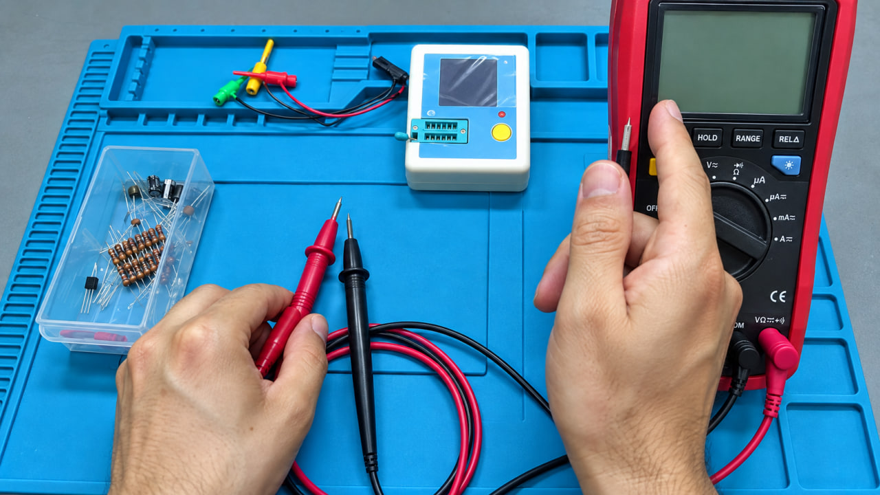
• Essential Test Equipment: Learn when to use a standard multimeter, ESR/component tester, regular probes, needle-tip probes, and alligator-clip attachments. Proper probe contact is important because loose connections and probe resistance can affect low-resistance readings.
• Measuring Resistors: Learn how to measure through-hole and SMD resistors in resistance mode, interpret readings in ohms, kilo-ohms, and mega-ohms, and account for resistor tolerance and meter accuracy. The lesson also explains how resistors behave in series and how to identify resistor values using colour bands or SMD markings.
• Testing Fuses and Potentiometers: See how a good fuse should show very low resistance, while a high-resistance or open reading indicates a faulty fuse. Learn how a potentiometer or trim pot changes resistance as it is adjusted.
• Checking Diodes: Use diode-test mode to measure a diode’s forward voltage drop and verify that it conducts in one direction only. The lesson covers standard diodes, Zener diodes, LEDs, Schottky diodes, and bridge rectifiers.
• Testing Bridge Rectifiers: Learn how to test the four internal diodes of a bridge rectifier through its positive, negative, and AC terminals, an important procedure for diagnosing faulty laptop adapters and power supplies.
• Measuring Capacitors: Understand why capacitors should generally be removed from the circuit before capacitance testing. Parallel, series, and surrounding circuit paths can produce misleading in-circuit readings. Learn to observe polarity on polarized capacitors and to discharge capacitors safely before testing.
• Identifying Faulty Capacitors: Learn the common signs of capacitor failure:
o Physical swelling, leakage, or bursting
o A short-circuit reading in continuity mode
o Capacitance significantly below its rated value
o Excessive ESR despite apparently normal capacitance
• Understanding ESR: Learn what Equivalent Series Resistance (ESR) means and why it is important. A capacitor can measure close to its rated capacitance but still be unreliable if its ESR is too high. High ESR can cause poor filtering, voltage instability, excess heat, and intermittent circuit faults.
• Testing Inductors: Learn how to check inductors by measuring their DC resistance (DCR). In laptop repair, a very low resistance is commonly expected. Physical damage, discoloration, cracking, or abnormally high resistance may indicate a defective inductor. The lesson also explains the difference between resistance measurement and true inductance measurement in µH or mH.
• Testing BJTs: Learn how to use diode mode to identify and test NPN and PNP bipolar transistors by checking their internal PN junctions. The method helps locate the base terminal, determine transistor type, and identify shorted or damaged junctions.
• Testing MOSFETs: Learn basic multimeter methods for checking N-channel and P-channel MOSFETs, including body-diode readings, gate charging, switching the channel ON and OFF, and performing quick continuity checks for shorts between Gate, Drain, and Source.
• Component Identification with an ESR Tester: See how a component tester can automatically identify unknown three-pin devices, distinguish between BJTs and MOSFETs, identify NPN/PNP or N-channel/P-channel types, and display values such as RDS(on), capacitance, ESR, resistance, or inductance.
This lesson builds the practical measurement skills needed for every stage of motherboard repair, from checking individual components and power rails to locating shorts and confirming whether a suspected component is healthy or faulty.
• Essential Test Equipment: Learn when to use a standard multimeter, ESR/component tester, regular probes, needle-tip probes, and alligator-clip attachments. Proper probe contact is important because loose connections and probe resistance can affect low-resistance readings.
• Measuring Resistors: Learn how to measure through-hole and SMD resistors in resistance mode, interpret readings in ohms, kilo-ohms, and mega-ohms, and account for resistor tolerance and meter accuracy. The lesson also explains how resistors behave in series and how to identify resistor values using colour bands or SMD markings.
• Testing Fuses and Potentiometers: See how a good fuse should show very low resistance, while a high-resistance or open reading indicates a faulty fuse. Learn how a potentiometer or trim pot changes resistance as it is adjusted.
• Checking Diodes: Use diode-test mode to measure a diode’s forward voltage drop and verify that it conducts in one direction only. The lesson covers standard diodes, Zener diodes, LEDs, Schottky diodes, and bridge rectifiers.
• Testing Bridge Rectifiers: Learn how to test the four internal diodes of a bridge rectifier through its positive, negative, and AC terminals, an important procedure for diagnosing faulty laptop adapters and power supplies.
• Measuring Capacitors: Understand why capacitors should generally be removed from the circuit before capacitance testing. Parallel, series, and surrounding circuit paths can produce misleading in-circuit readings. Learn to observe polarity on polarized capacitors and to discharge capacitors safely before testing.
• Identifying Faulty Capacitors: Learn the common signs of capacitor failure:
o Physical swelling, leakage, or bursting
o A short-circuit reading in continuity mode
o Capacitance significantly below its rated value
o Excessive ESR despite apparently normal capacitance
• Understanding ESR: Learn what Equivalent Series Resistance (ESR) means and why it is important. A capacitor can measure close to its rated capacitance but still be unreliable if its ESR is too high. High ESR can cause poor filtering, voltage instability, excess heat, and intermittent circuit faults.
• Testing Inductors: Learn how to check inductors by measuring their DC resistance (DCR). In laptop repair, a very low resistance is commonly expected. Physical damage, discoloration, cracking, or abnormally high resistance may indicate a defective inductor. The lesson also explains the difference between resistance measurement and true inductance measurement in µH or mH.
• Testing BJTs: Learn how to use diode mode to identify and test NPN and PNP bipolar transistors by checking their internal PN junctions. The method helps locate the base terminal, determine transistor type, and identify shorted or damaged junctions.
• Testing MOSFETs: Learn basic multimeter methods for checking N-channel and P-channel MOSFETs, including body-diode readings, gate charging, switching the channel ON and OFF, and performing quick continuity checks for shorts between Gate, Drain, and Source.
• Component Identification with an ESR Tester: See how a component tester can automatically identify unknown three-pin devices, distinguish between BJTs and MOSFETs, identify NPN/PNP or N-channel/P-channel types, and display values such as RDS(on), capacitance, ESR, resistance, or inductance.
This lesson builds the practical measurement skills needed for every stage of motherboard repair, from checking individual components and power rails to locating shorts and confirming whether a suspected component is healthy or faulty.